Space solid propellant engines. The first solid fuel
TYPES OF UNSTABLE WORKING PROCESSES IN CS solid propellant rocket motors.
1. A process with self-oscillations of operating parameters, the characteristics of which go beyond the established limits, is called unstable. The instability of solid propellant rocket motors significantly reduces the reliability of engines, deteriorates their intra-ballistic characteristics, increases the development time, increases the cost of the aircraft, can damage on-board equipment, destroy the engine and the aircraft.
Possible results of the occurrence of an unstable operating process in the combustion chamber of a solid propellant rocket engine are illustrated in Fig. 1: failure of the rocket control system due to high amplitudes of mechanical vibrations transmitted from an unstable engine (top pictures); off-design trajectory resulting from excessive ballistic disturbances of engine parameters (average drawings); mechanical destruction of the engine due to a continuous increase in pressure in the combustion chamber (lower pictures).
Fig.1. Some results of solid propellant rocket engine instability:
1 - pressure fluctuations; 2 - actual value; 3 - design value
Unstable operating processes in the combustion chamber of a solid propellant rocket engine manifest themselves primarily in the form of low- and high-frequency uncontrolled pressure oscillations in the longitudinal, transverse, transverse and tangential directions with a frequency from several hertz to several tens of kilohertz. Examples of oscillatory modes of solid propellant rocket motors are shown in Fig. 2 and 3 in the form of graphs constructed from the results of experiments in coordinates ![]() (dimensionless pressure deviation) - (dimensionless engine operating time).
(dimensionless pressure deviation) - (dimensionless engine operating time).

Fig.2. Typical forms of low-frequency pressure fluctuations in the combustion chamber of a solid propellant rocket engine:
a - qualitative picture of the development of oscillations; b - development of oscillations caused by a pressure peak during charge ignition; c - low-frequency instability due to a pressure peak during startup, leading to extinguishing the charge with its subsequent ignition; d - oscillogram of tests of a solid propellant motor, prone to unstable oscillations with a very low frequency; d - low-frequency pressure fluctuations during the startup period

Rice. 3. Evolution of high-frequency oscillations in coordinates:
![]() - dimensionless time τ.
- dimensionless time τ.
As can be seen, these modes are very different from the conditions of stable operation of the engine, when all operating parameters change relatively slowly and smoothly during the combustion of the charge and only as a consequence of changes in its internal geometry.
Various unstable operating modes of solid propellant rocket motors are realized in the presence of disturbances that form pressure waves. As a result, deviations in the flow characteristics of combustion products arise, which interact in an unsteady manner with the parameters of the combustion surface. The equilibrium flow of processes is disrupted, since under the influence of pressure waves local changes in the rates of heat release and gas formation occur. The frequency and shape of the waves observed in this case depend on the interaction mechanism and the internal geometry of the engine chamber. The flow of combustion products is limited mainly by the combustion surface, as well as by the curved bottom wall with a heat-protective coating, on the one hand, and the critical section of the nozzle, on the other.
In the case when fluctuations of heat and gas release are in the appropriate phase and have sufficient amplitude to overcome energy losses, the intensity of the waves increases. This process of amplification continues until the conditions for a new balance of energy appear.
These conditions are established depending on specific physical parameters over a very wide range of wave intensities. Usually, some particular fashion predominates. All this greatly complicates the mathematical description of the oscillatory processes occurring in the combustion chamber.
As a rule, under conditions of pressure fluctuations in the chamber, the combustion rate of solid fuels increases. This leads to an increase in pressure and thrust compared to the design mode and a decrease in the charge combustion time. The thrust force, in addition, receives an oscillatory component, which is transmitted to the rocket body, which is the reason for the failure of the equipment, including the control system, etc. With a significant increase in pressure, the engine (or charge) can be destroyed. If the engine is stable, then the resulting oscillations either have an acceptable amplitude, or simply die out due to the predominance of energy dissipation over the energy of the disturbing forces.
2. Currently, the most common is the separation of periodic oscillations in solid propellant rocket motor chambers according to their frequency. Highlight low frequency And high frequency vibrations in the combustion chamber.
Low-frequency instability is determined by self-oscillations in the combustion chamber with a frequency less than the minimum natural acoustic frequency. The range of such low frequencies is limited to oscillations with a frequency of no more than 100 Hz. With low-frequency oscillations, the pressure in the combustion chamber changes equally at all points of its volume, i.e., this volume appears as one whole. Since the characteristic that mainly determines the region of instability of this type is the reduced length of the chamber, equal to
where is the volume of the combustion chamber; - the area of the critical (minimum) section of the nozzle, then this type of instability is often called - instability (especially in foreign literature). -instability occurs most often in small solid propellant rocket motors (at small } and at relatively low pressures.
High-frequency instability is determined by self-oscillations in the combustion chamber with a frequency close to one of the natural acoustic frequencies of the combustion chamber.
During high-frequency instability, acoustic waves propagate in the combustion chamber, amplifying when reflected from the burning surface due to the influx of acoustic energy from the burning surface (Fig. 4). Typically, pressure fluctuations during acoustic instability gradually increase from very small amplitude values to large ones (see Fig. 3). Such oscillations are called divergent.

Fig.4. Scheme of interaction between the combustion zone and acoustic waves
Decaying acoustic vibrations have a gradually decreasing amplitude. For periodic(or regular) oscillations are characterized by constant amplitude and frequency.
Periodic acoustic vibrations in the combustion chamber can be longitudinal And transverse.
Longitudinal- these are high-frequency vibrations along the axis of the camera (see Fig. 5 A).
 Transverse vibrations in the combustion chamber are high-frequency vibrations in a plane perpendicular to the axis of the chamber. Depending on the direction of the oscillatory movement, these vibrations are divided into tangential, radial And mixed transverse vibrations (see Fig. 5b,c).
Fig.5. Three classes of acoustic waves:
a - longitudinal vibrations with the lowest frequency (where a - average speed sound in volume); b - tangential transverse ( ![]() ); c - radial transverse (
); c - radial transverse ( ![]() ).
).
In its simplest form, an oscillatory system can be described by the following wave equation:
![]() (2)
(2)
where is a small pressure disturbance; A- speed of sound; τ - time.
General solution this equation in cylindrical coordinates for absolutely rigid walls of the combustion chamber has the form
Where k, m, n- integers; I m- Bessel function of the first kind of order T; -k th root of the equation; and are arbitrary constants; and are arbitrary phase angles; - circular frequency; D- chamber diameter; φ And r- cylindrical coordinates.
In this case, the formula for determining the natural frequencies of acoustic vibrations of combustion products in the chamber in the general case has the following form:
![]() (4)
(4)
Members with m = 0;n ≠ 0 ; k = 0 correspond to longitudinal modes with frequency
Members with m = 0;n = 0 ; k≠ 0 correspond to radial modes with the frequency of the first radial mode of vibration ( k =1):
Members with k = 0 , n = 0 , m ≠ 0 - tangential modes with the frequency of the first tangential mode of vibration ( m =1):
Note that longitudinal-transverse vibrations can also be observed in the combustion chamber.
In engines with a large length-to-diameter ratio (L/D> >10), self-sustaining longitudinal oscillations can occur in the combustion chamber in the presence of a disturbance exceeding a certain critical value (high-frequency transverse oscillations arise spontaneously, starting from very small amplitudes in the presence of soft excitation of self-oscillations. ). Note that longitudinal acoustic modes occupy the frequency range 100...1000 Hz.
Acoustic vibrations with a developed amplitude require research using nonlinear equations. That's why they are called nonlinear, unlike linear vibrations of small amplitude, which are analyzed using linear differential equations.
The limiting case of instability of the working process in a solid propellant rocket engine is a sharp increase in the values of all parameters of the combustion products due to the occurrence of a strong shock wave, at which combustion turns into detonation.
All these types of instability belong to dynamic instability, since they are determined by non-stationary combustion processes, in contrast to static instability, when the breakdown of stable combustion followed by an unlimited increase in pressure in the combustion chamber occurs due to the sharp sensitivity of the stationary combustion rate to changes in pressure. Instability of this type occurs when v>l. Therefore, in practice, fuels with v 3.
General information about the mechanisms of oscillations in solid propellant rocket motors. In real conditions, unstable solid propellant rocket motor modes cause complex mixed oscillations of various constantly changing frequencies. For example, in the engine of the second stage of the Poseidon rocket, oscillations with harmonics of nine different frequencies were observed during the first 10 s. During the first two seconds, oscillations with a frequency of 300 Hz appeared in the solid propellant rocket motor of the Minuteman II rocket, which turned into oscillations with a frequency of ~500 Hz, lasting 10...15 s. In the solid propellant rocket motor of the Minuteman III rocket, immediately after launch (after 0.1...0.2 s), oscillations with frequencies of ~850 Hz appeared for 4 s, and then with ω = 330 Hz (lasting ~ 12 s). All these fluctuations were of significant intensity and, if they did not lead to an accident, they created real preconditions for damage to the on-board electronic equipment. Known mathematical models of an unstable working process in a solid propellant rocket engine chamber cannot yet sufficiently fully describe real processes. Thus, in particular, the given wave equation (2) is written for an ideal cylindrical cavity filled with a homogeneous gas mixture with a low speed of movement and a small amplitude of gas oscillations. This equation does not take into account the variability of the cavity volume due to charge burnout, the variability of the composition of combustion products by volume, the possibility of vibrations of the chamber walls and charge, the unevenness of processes in the combustion zone of solid rocket fuels, etc. Consequently, it cannot explain the reasons for the occurrence and maintenance of vibrations in the chamber. A solid propellant rocket motor is a self-oscillating system, which includes a part of the chamber filled with combustion products, an energy source and a mechanism* (or a number of mechanisms) that supplies energy to the oscillatory system. The most important issues that require clarification when studying the instability of solid propellant rocket motors are identifying the mechanism of excitation (or suppression) of oscillations, determining the boundaries** or threshold for the occurrence of oscillations, their amplitude and frequency. In early studies, it was believed that the mechanism of low-frequency instability is determined by the lag of changes in the burning rate (due to the temperature gradient at the surface) with respect to perturbations in the pressure and flow of gases from the chamber. It is currently believed that the mechanism of excitation of non-acoustic low-frequency oscillations can be explained from an acoustic point of view. Therefore, the reasons for the instability of solid propellant rocket engines in the general case should be sought in the interaction of the cavity of the combustion chamber and the surface of the burning fuel (see Fig. 4). The combustion rate increases with increasing pressure, therefore, with small pressure fluctuations near the combustion surface, a local increase in the combustion rate occurs (due to an increase in heat flow into the combustion zone), which contributes to a new increase in pressure; the latter again increases the burning rate, etc. As a result of this, the amplitude of the oscillations increases, which leads to instability. In addition to this factor, the cause of oscillatory modes is the presence of a pulsating heat flow going to the surface of the charge. Such heat flow pulsations determine the presence of a damped temperature wave inside the solid fuel, as a result of which at the crests of this wave the rate of fuel decomposition (according to the exponential Arrhenius law) will exceed the normal combustion rate to a greater extent than slow down at the depressions. The overall effect of such a pulsating heat flow leads to an increase in the rate of decomposition. Therefore, if the fuel is characterized by an exothermic reaction that enhances the temperature wave, then such fuel is more sensitive to high-frequency fluctuations. Obviously, in the case of endothermic reactions of fuel, temperature waves will be self-damping. All these phenomena are taken into account in various theoretical models of oscillatory modes of solid propellant rocket engines. Such a qualitative picture of the occurrence of unstable operating modes of solid propellant rocket motors, however, in a number of cases cannot explain the reason for the appearance of oscillations. * In this case, the mechanism also means physical and chemical processes united by a causal relationship. ** The stability boundary of the working process in the combustion chamber is a set of values of operating parameters that separates the areas of stability and instability HIGH-FREQUENCY INSTABILITY OF SOLID MOTOR MOTORS 1.
From a theoretical point of view, solving the problem of high-frequency instability of a solid propellant rocket engine comes down to solving the acoustic wave equation, taking into account the acoustic internal characteristics of the chamber (naturally, with the corresponding boundary conditions). The accumulated experimental material made it possible to identify the following features specific to this regime: a) acoustic vibrations with large amplitudes appear in the chambers of solid propellant rocket motors, sometimes reaching the average operating pressure; b) such oscillations appear, as a rule, sporadically, and during engine operation one specific oscillation mode or several may be excited in order to disappear, and after some time of stable operation reappear in a new combination of modes, which may or may not include Not c) to reproduce the frequency-time spectrum of an unstable mode, it is necessary to repeat the test conditions with scrupulous accuracy while maintaining the same fuel composition, external conditions, etc.; d) quite often, large amplitude oscillations are accompanied by an increase in the average fuel combustion rate. 2.
To theoretically describe such a complex phenomenon as high-frequency instability of a solid propellant rocket motor, it is necessary to consider the chamber as an acoustic resonator having many resonant frequencies at which it will be most easily excited. Will any small disturbance excite one or more Fig.6. Factors affecting engine stability Factors affecting engine stability include: A - combustion surface, relating gas pressure and velocity; B - thermal radiation; C - viscoelastic losses in fuel; D-effects in the combustion chamber, including the damping effect of particles in the flow, other viscothermal damping, relaxation damping, residual chemical reactions; E - engine housing, which determines the effects of viscothermal losses on the walls, external influences, etc.; F - nozzle damping effects. The combustion surface is a source of acoustic energy, and all other factors are its losses. Since instability is possible until the acoustic losses exceed the acoustic gains, the determination of acoustic losses is by no means unimportant. It is of interest to know the acoustic characteristics of the combustion zone, which can be quantitatively described by the specific acoustic conductivity of the combustion surface or the transfer function of the fuel. The characteristics of solid fuel are determined from an acoustic point of view by two moduli of elasticity, the real parts of which are related to the speed of propagation of disturbances due to shear and expansion, and the imaginary parts express the energy losses caused by these disturbances. As for the combustion zone, its thickness is significantly smaller compared to centimeter or longer acoustic wavelengths, and therefore it can be considered to belong to the surface. This allows the combustion surface and other boundary surfaces of the chamber to be characterized by their acoustic conductivities, the real part of which describes the amplification or attenuation of acoustic vibrations. 3.
Theoretical consideration of the problem of high-frequency instability requires solving equations that describe physical and chemical processes, taking into account the above effects. These processes occur in a volume containing solid and gaseous media, separated by a complex boundary capable of supplying additional energy to the field of acoustic vibrations. In this case, the main issue becomes the choice of those forms of the process on which to focus attention; the choice of assumptions and simplifications that should be made in the mathematical description of the model so that it is sufficiently real, amenable to clear interpretation and allows it to be processed mathematically. There are two directions on this path. One is associated with the study of small amplitude oscillations on the stability boundary, and the solution of problems is carried out using the analysis of small disturbances, leading to linear differential equations. The main question in linear theory is whether the amplitude of random small pressure disturbances, which always occur in a rocket engine, will increase or not. Stability in the presence of small disturbances is a necessary but not sufficient condition for stability in general. For this reason, the second direction also explores oscillations with developed amplitude, which are described nonlinear differential equations. Ministry of Education of the Russian Federation South Ural State University {
Yu.Yu. Usolkin}
Calculation of energy-mass and dimensional characteristics of solid propellant rocket motors. Methodical manual. The manual presents a simplified methodology for design assessment of solid propellant rocket motor parameters, which allows one to quickly and with a sufficient degree of reliability (for the initial stages of rocket design) determine the energy and overall-mass characteristics of a solid fuel rocket engine. The manual is compiled on the basis of the methodological provisions set out in , , and is intended for practical work on determining the characteristics of solid propellant rocket engines and a course project on designing a solid fuel aircraft. Initial data: Fuel composition and its passport parameters under standard conditions (P K / P a = 40/1); –specific thrust impulse [m/s]; 2. Required energy characteristics of the engine (obtained from the results of ballistic design of the rocket): Р П – engine thrust in vacuum [kN]; 3. Motor diameter [m]. 4. The diagram of a typical solid propellant rocket motor is considered (shown in Fig. 1). Sequence of calculations. the reduced standard thrust impulse is determined here: a – percentage of Al content in the fuel; We accept the condition of constant average pressure in the combustion chamber during engine operation, i.e. r k ≈ r k av = const. The engine operating time, fuel consumption and available fuel reserve are determined: charge diameter burning vault thickness here: d in – diameter of the internal channel, taken d in here, k is a coefficient that takes into account the unused fuel supply, depends on the shape of the charge, the engine circuit, the shape of the channel (k=1.01÷1.05) The geometric parameters of the engine are determined: thermodynamic complex critical section area of the nozzle here: χ – heat loss coefficient, μ–flow coefficient nozzle throat diameter degree of geometric expansion of the nozzle nozzle exit area nozzle outlet diameter total nozzle length (see Fig. 1) here: β с – half-opening angle of the conical nozzle (for conical nozzles usually β s =12÷20 0) length of the recessed part of the nozzle here: f – takes into account the degree of recession (usually f=0÷0.3) nozzle extension length diameter of the nozzle at the exit from the combustion chamber Here length (height) of the front bottom Here: length (height) of the nozzle cover (rear bottom) Here: length of the cylindrical part of the combustion chamber Here: relative charge length 5. The mass characteristics of the engine are determined mass of the cylindrical part of the combustion chamber here: ρ c – density of the material [kg/m 3 ] σ in – ultimate strength of the material [ f – safety factor Weight of the front and rear (nozzle cover) bottoms (neglecting the dimensions of the cutouts for the nozzles) mass of the armor coating (depends on the area of the armored surface of the charge, the thickness of the armor, the density of the material ρ b) here: α br =0.04÷0.1 [mm/s] – constant coefficient for a given armor coating, mass of nozzles here: k s – coefficient depending on the shape of the charge and the size of the channel, k s =2.03÷3.40; α с – coefficient of proportionality of the average thickness of the nozzle wall with thermal protection to the diameter of the combustion chamber, α с =0.004÷0.008. thermal protection mass here: ρ tз – density of the heat-protective coating; The thickness of the heat-protective coating can be determined by the dependence and TZ is the thermal diffusivity coefficient of thermal protection, according to statistics and tz =(0.5÷1.0)·10 -6 [m 2 /s], weight of attachment points for bottoms, igniter and assembly parts here: K t – temperature coefficient, depending on the type of fuel and charge design, you can take K t = 1.2. engine weight 6. The mass characteristics of the control body are determined. We consider the case of creating control forces using an oscillating engine nozzle here: m рп – mass of the steering gear (steering gears and control valves); m BIP – mass of the on-board power source (working fluid, tank and control valves); m crepe – mass of fastening units (we include m uk in the mass). The mass of the steering gear (RS) depends on the required power, which is determined by the level of engine thrust, the size and inertial characteristics of the rotating (swinging) part of the nozzle, the type of nozzle suspension, the amount of control force, i.e. nozzle deflection angle, and speed. As a first approximation, one can take The weight of the on-board power supply depends on the power of the RP, the operating time of the engine, the design of the container and the structural material used Here: τ – engine operating time, s, α k is the coefficient of perfection of the tank design, taking into account the presence of reinforcement. 7. The mass of the propulsion system is determined An example of calculating the energy and overall-mass characteristics of a solid fuel combustion engine. Initial data: We choose polyurethane fuel. Composition: ammonium perchlorate (NH 4 ClO 4) – 68% polyurethane –17% aluminum – 15% Fuel specifications: R UDST =2460 [m/s]; ρ T =1800 [kg/m 3 ]; T ST =3300 [0 K]; R ST =290 [J/kg°]; k ST =1.16; U(p k)=5.75r k 0.4 [mm/s] Obtained from ballistic design: R P =1000Kn; p k =10MPa; p a =0.06 MPa. 3. Engine (rocket) diameter D p =1.6 m. Sequence of calculations. 1. Determine the specific impulse of the engine thrust in vacuum: We determine the consumption characteristics and fuel reserves of the solid propellant rocket engine. u=5.75ּ10 0.4 =14.43 mm/s 3. Determine the geometric parameters of the engine: 4. Determine the mass characteristics of the engine. To manufacture the engine housing, we will select an organoplastic with a tensile strength σ in = 1400 MPa and a density ρ m = 1400 kg/m 3. To manufacture the nozzle we use a titanium alloy with a density ρ c = 4700 kg/m 3 . To protect against thermal influences, we use TZP based on a combined binder with ρ TZP = 1600 kg/m 3 . To armor the charge, we will choose a coating based on phenol-formaldehyde resin with a density ρ br = 1300 kg/m 3 . mass of the cylindrical part of the combustion chamber Bottom weight armor mass mass of nozzles (here the average density of the nozzle material is obtained under the assumption that the ratio of the thickness of the nozzle wall and the heat-protective coating is 1:2). thermal protection mass weight of attachment points engine weight 5. Determine the mass of the control Let us assume that the flow rate of the working fluid through the RP is equal to 6.Weight of the propulsion system Thus, all the necessary solid propellant parameters for further rocket design have been determined. Literature. Design and testing of ballistic missiles. Ed. V.I. Varfolomeev and M.I. Kopytov, publishing house MO, M., 1970 – 392 pp., ill. Pavlyuk Yu.S. Ballistic missile design. Textbook for universities. Publishing house ChSTU, Chelyabinsk, 1996 – 114 pp., ill. When considering work processes in a solid propellant rocket engine, three characteristic periods are distinguished (Fig. 2.3): engine output to operating mode t; this mode includes ignition delay time the main period of engine operation, called the charge burning time t 3
;
this area accounts for the bulk (more than 90%) of the total working time; pressure decay time t The total operating time of the engine is determined by the sum of these periods: When calculating the process during the period when the engine reaches operating mode, the equations of unsteady (wave at the initial stage) flow of combustion products of the igniter fuel and the main charge are considered, taking into account afterburning in air oxygen, heating and flashing of the fuel, and initial heating of structural elements. To calculate the main period, the equations of gas flow and combustion of a solid fuel charge are used in a quasi-stationary approximation. A geometric calculation of charge burnout is preliminarily carried out. The basis of the geometric calculation of changes in the area of the burning surface S(e)
and channel flow area F(e)= In the main section at low gas flow velocities and low dp/
dt
the mass balance equation is satisfied with sufficient accuracy in the form up T S
=pF In case S We have Restriction on the initial thrust-to-weight ratio of the stage n 0
= The intra-ballistic and traction characteristics of solid propellant rocket engines change noticeably due to deviations of the charge and engine parameters from the nominal ones. Relative variation in pressure or flow Where Rice. 2.3. Change in pressure in the solid propellant motor duringtime. If there is no temperature control, then Rice. 2.4. Moving the burning surface of the charge: 1 - armor coating; 2 - solid fuel; 3 - position of the burning surface when the thickness of the arch burns out e. Taking into account the variations, the maximum pressure in the engine is equal to In the next approximation, inhomogeneities in the combustion rate are taken into account due to changes in pressure and gas flow velocity along the channel, as well as due to local deviations in the physical and mechanical properties of the fuel, its temperature and deformation (see Section 1.2). The section of pressure decline during charge burnout begins when the combustion front approaches some point on the surface corresponding to complete burnout of the roof. In this area, the remaining fuel charge burns out and the products of fuel combustion and decomposition of coatings flow out. To assess dependency S Solid rocket motor is a rocket engine running on solid rocket fuel. Solid propellant rocket motors are widely used as launch and propulsion engines for missiles of various classes and rockets. In aviation and space technology they are used as aircraft take-off accelerators, for separating and removing spent stages of space rockets, ensuring a soft landing when airdropping cargo, in emergency rescue systems for aircraft crews, etc. The common elements of any solid propellant rocket engine are: housing 1 (combustion chamber), solid rocket fuel charge2, nozzle block 3, igniter 4, electric igniter 5 and thermal protection. The fuel charge is either loosely inserted into the combustion chamber in the form of one or several blocks, or secured to its walls by pouring fuel into the chamber in a semi-liquid state, followed by its solidification. The change in the combustion surface over the operating time of the solid propellant rocket engine determines the nature of the change in engine thrust (thrust is constant, increases, decreases, changes stepwise). Channel-slot, star-shaped, end and other charges are used. Areas of the surface that need to be excluded from the combustion process are armored with coatings made of rubber-fabric materials. High-strength steels, aluminum and titanium alloys, as well as composite materials are used to manufacture solid propellant rocket motor housings. The ignition device is located, as a rule, on the front bottom of the housing and serves to create pressure and ignite the fuel charge. The nozzle block converts the thermal energy of fuel combustion products into the kinetic energy of the gas jet. The nozzle block insert, which forms the nozzle neck, as the most heat-stressed element of the solid propellant rocket engine, is made of refractory materials (graphite, tungsten, molybdenum) or erosion-resistant press materials. For thermal protection of the internal walls of the solid propellant rocket motor housing and the nozzle bell, glass, carbon and organoplastics, press materials based on asbestos and phenolic resins are used. The main requirements for thermal protection are low thermal conductivity and low rate of destruction when exposed to a high-temperature gas flow. The solid propellant rocket motor may have additional devices used to control the thrust vector. The thrust is changed by adjusting the critical section of the nozzle or by opening the counter-thrust nozzles; stopping the burning of a fuel charge (for example, to ensure a given speed at the end of the active part of the trajectory) is achieved by abruptly releasing pressure in the combustion chamber by opening a special windows or coolant injection. The direction of the thrust vector is changed using gas rudders placed in the outflowing gas stream, rotary nozzles, asymmetrical liquid injection or gas injection into the supersonic part of the nozzle, etc. Despite the relatively low specific thrust impulse (2.5-3 km/s), solid propellant rocket engine have creatures, advantages: the ability to obtain high thrust (up to 12 MN or more); high degree of readiness for launch, possibility of long-term storage; simplicity and compact design; high reliability and ease of operation. A solid fuel rocket engine consists of layers of fuel located transversely to the charge axis and is equipped with an initiation system that ensures alternate detonation of the layers of matter. Layers of fuel with high detonation ability, the thickness of which is significantly greater than the critical thickness of detonation of the fuel, are interspersed with other layers of fuel from a substance with low detonation ability, the thickness of which is significantly less than its critical thickness of detonation, but sufficient to prevent the transfer of detonation from the previous layer with high detonation ability of the subsequent layer with high detonation ability. Layers of fuel with high detonation ability and layers of fuel with low detonation ability are bonded to each other. The initiation system ensures alternate detonation of layers of matter with a given constant or variable frequency. The invention makes it possible to create a rocket engine with a high specific thrust impulse and the ability to vary thrust over a wide range. 1 ill. Solid propellant rocket engines (solid propellant rocket motors) have one significant advantage over liquid propellant engines. Solid propellant engines are extremely simple in design: a housing filled with solid fuel, and the housing has a hole with a nozzle. Fuel combustion occurs in a housing under pressure. It is the pressure that ensures stable combustion of the fuel. When moving to higher calorie (energy) fuels, for their stable combustion, as a rule, even greater pressure is required. All this leads to the need to make the hulls more durable, and therefore heavier, which partially reduces the effectiveness of the transition to higher-calorie fuels. Solid fuel rocket engines are well known and widely used in various designs and versions depending on the purpose. For all versions of such engines, it is necessary to have a combustion chamber with a nozzle block and a charge of solid fuel placed in the chamber. By burning the charge, the potential energy stored in it is released, which is accumulated in the resulting gases, heated to high temperatures. Depending on the ratio of the gas inflow from the burning charge of gases and their gas outflow through the flowing cross-section of the nozzle block, a certain pressure is established in the semi-closed volume of the combustion chamber. Under the influence of pressure, gases flow through the nozzle, accelerating to high speeds, acquiring a certain amount of movement. Accordingly, the rocket acquires the same amount of motion. Potential chemical energy is only partially converted in the engine into useful mechanical energy of movement, and is partially lost in the form of heat carried away by uncooled gases. Solid propellant motor diagram 1 - charge of solid rocket fuel, 2 - chamber body, 3 - recessed nozzle, 4 - igniter Design of the main components of the solid propellant rocket engine: Let us note the role of the listed components in the operating process of the remote control (gas generator). As noted above, the source of energy and gaseous combustion products in the systems under consideration is a fuel charge, in which, when heated to a certain temperature, called the ignition (flash) temperature, a chemical reaction begins with the release of gaseous combustion products with a large amount of heat. Solid propellant rocket motor with inserted charge: 1
- cylindrical shell of the solid propellant rocket motor housing; 2
. - front bottom;., 3 - nozzle bottom; 4
- charge attachment points; 5 - fuel charge; 6 - ignition system; 7 - nozzle; 8
-
nozzle plug; 9
-
heat-protective coating and (or) protective-fastening layer The PS housing, together with both bottoms, limits the volume in which fuel combustion occurs, ensuring a given level of implemented intra-ballistic parameters and acting as a supporting structure. The outflow of combustion products is carried out through a supersonic nozzle, the role of which is to increase the efficiency of converting the thermal energy released in the solid propellant rocket engine chamber into the kinetic energy of the products flowing out of the chamber. The shape of the nozzle ensures the acceleration of combustion products to supersonic speeds, which helps to increase the thrust of the propulsion system. It should be noted that at present there are small-sized solid fuel propulsion systems in which there is no nozzle block as such. An increase in the design thrust is achieved by changing the profile of the fuel charge channel in the vicinity of the outlet section, which is chosen close to the profile of the nozzle block. In a number of cases, such solid propellant rocket motors ensure that the requirements of the technical specifications for energy performance are met, while remaining as simple as possible. Since the temperature of the combustion products in the solid propellant rocket engine chamber is very high and can reach a level of 3500...3700 K, and the heat flow values are 10 6 ...10 7 W/m 2, there is a need to protect the design elements of the engine from overheating and, therefore, from destruction during the working period. This function is provided by heat-protective coatings that can be applied to the internal surfaces of the body components, starting from the front bottom, right up to the outlet section of the supersonic nozzle. Heating of the surface of the fuel charge to the temperature at which the chemical reaction begins is ensured by the ignition system. The simplest and most frequently used method in practice is the implementation of an ignition system using black powder or a pyrotechnic composition, housed in a housing that can remain strong during the operating period or is destroyed. The hitch is ignited using an electric igniter. Fastening of the inserted charges is ensured, for example, by diaphragms located in the vicinity of the joints of the front and nozzle bottoms with the shell of the solid propellant rocket engine. Strongly fastened structures require, when there is a large difference in the coefficients of thermal expansion of the body and fuel materials, the use of an intermediate layer between the body and the fuel - the so-called protective-fastening layer. To regulate the magnitude and direction of thrust, rocket engines may contain steering elements, units that provide changes in the geometry of the nozzle path, etc. During the storage period of the solid propellant rocket engine and until a certain point in engine operation, its internal volume must be plugged with a membrane that collapses at a given pressure of the combustion products in the chamber of the propulsion system. The presence of a membrane is due to the need to protect the internal surfaces of the chamber and charge from atmospheric influences, mechanical contamination, and in some cases, to retain gas in the internal volume of the chamber in a pre-launch state at a certain boost pressure. A solid fuel propulsion system (gas generator) can be characterized by the following set of parameters: fuel mass W T ; mass of the entire solid propellant rocket engine m c.d. and the mass of each node m i ; relative weight of the engine structure b c.d. , defined as the ratio of the unloaded mass to the solid propellant rocket mass x c.m. ; location of the center of mass separately for nodes, and in general for the entire solid propellant rocket engine design; density (coefficient) of filling the intra-chamber volume with fuel e w , defined as the ratio of the volume of the fuel charge to the internal volume of the chamber (from the front bottom to the plane of the critical section); thrust of the propulsion system and (or) the value of the mass second flow rate (P, T); operating time of the propulsion system f p ; total I and specific impulses I Y solid propellant rocket motor; overall dimensions - length L, overall engine diameter D
and by nodes. The listed set of parameters is not exhaustive and is not the only acceptable one. So, for example, instead of the bk.d parameter the following can be used: relative fuel supply; engine quality factor in d, etc. You can make connections between these three parameters: rocket engine airplane The listed set of parameters, along with the known area of application of the propulsion system, makes it possible to judge the efficiency of the solid propellant rocket engine, the advantages or disadvantages of developing any components. The most indicative parameters in this sense are b c. d and e w .
To date, the best values of these quantities have been obtained during the development of MX class intercontinental ballistic missiles (b c. d ~ 0.05...0.08; e w « 0.92...0.95). The work, in particular, is devoted to a description of the working processes occurring in the chamber of a solid fuel rocket system. Let us note a set of basic processes that are consistently implemented during the operation of the solid propellant rocket engine in a volume sufficient for a preliminary understanding of the intra-chamber processes. For definiteness, we will consider the diagram presented in Fig. 1. : The working process in the solid propellant rocket engine chamber begins with the supply of electrical voltage to the electric igniters of the squib cartridges. The force of the flame from the flammable squib cartridge ensures the ignition of the ignition composition, consisting of black powder or a mixture of black powder with a pyrotechnic composition. Combustion of the ignition composition most often occurs in a closed volume of a durable housing at a pressure greater than the pressure level in the combustion chamber. The combustion products of the ignition composition enter the chamber through holes in the igniter body, which can be pre-profiled and plugged at the initial time. The influx of mass into the front volume of the solid propellant rocket engine leads to an increase in pressure in it and the formation of a compression wave moving to the nozzle volume. The speed of propagation of a compression wave in relation to the parameters of the gas in front of the wave can be either subsonic or supersonic. Following the wave, high-temperature combustion products of the ignition composition spread into the free volume of the engine chamber, heating the surface of the fuel charge due to convective, radiant and conductive heat transfer. After the compression wave reaches the plane in which the plug is placed, the intra-chamber process can develop according to two schemes Distribution of the pressure field along the length of the chamber at different times when the plug collapses: 1, 2, 3
-
movement of the compression wave from the front bottom to the nozzle (the plug is not destroyed); 4, 5
-
development of the process after the destruction of the plug Distribution of the pressure field along the length of the chamber at different times with a non-destructive plug: 1, 2, 3
-
movement of the compression wave from the front bottom to the nozzle; 4
- the compression wave reaches the plane of the plug; 5, 6 - development of the process after reflection of the compression wave from the plug Measuring pressure in the solid propellant rocket motor chamber during operation: Ro- initial pressure in the engine chamber; R ZG
-
nozzle plug destruction pressure; Pst - operating pressure level of combustion products in the chamber; ABOUT- start of the process; 1
- moment of destruction of the plug; 2
- moment of fuel ignition; 3
-
time corresponding to flame propagation along the fuel surface; 4
-
time for the engine to reach operating mode; 5 - end of the quasi-stationary period of engine operation; 6 -
end of engine operation. The plug is destroyed, the pressure level in the chamber is approximately equalized and remains close to constant until the moment when the surface of the fuel charge begins to connect to the combustion. The development of the process according to this scheme is presented in Fig. 2; The destruction of the plug is designed for high pressure values. This fact leads to the reflection of the compression wave from the right boundary of the engine and its propagation in the opposite direction. Due to the decrease in the speed of movement of combustion products in the free volume of the chamber, the intensity of the fuel charge heating process decreases, which leads to an increase in the period for the solid propellant rocket engine to reach the quasi-stationary operation mode. The development of the process according to this scheme is presented in Fig. 3. Ignition of the fuel charge occurs at the point in time when, in the surface layer of the fuel charge with a thickness measured in microns, a temperature and temperature gradient corresponding to certain critical conditions ensuring stable combustion of the fuel are reached. The spread of flame over the surface of the fuel charge, depending on the ignition conditions and the geometry of the solid propellant rocket engine, can occur at speeds of 1...300 m/s. The change in pressure in the front volume of the remote control over the entire period of operation is shown in Fig. 4. The main operating impulse is provided by the propulsion system on the curve section 4
-5.
The shutdown of the solid propellant rocket motor occurs either after the fuel charge is burned out, or forcibly using a thrust cut-off unit. To date, solid propellant rocket motors have achieved noticeable perfection, which has led to their widespread use in practice: the mass of a solid propellant rocket engine can currently be several grams or hundreds of tons; Solid propellant rocket engines can currently be used as an actuator for emergency shutdown of gas and oil transportation systems through pipelines. At the same time, solid propellant rocket engines can be used to launch large payloads into outer space; the specific impulse of solid rocket fuels has come very close to the specific impulse of liquid fuels and reached values of 3000…..3500 m/s; the mass perfection coefficient of the best modern solid propellant rocket engines reaches 0.05...0.10, and the filling factor of the intra-chamber volume is close to 0.90...0.95. Further improvement of solid propellant rocket engines will continue to consist of improving the energy characteristics of fuel compositions and increasing the specific strength of the structural materials used. In particular, it can be noted that a promising direction is the use of solid propellant rocket engines with separate placement of fuel components. An urgent task is to expand the scope of use of solid propellant rocket motors to the area of propulsion systems with deep thrust control, with the possibility of reusable inclusion of solid propellant rocket motors, etc. The development of solid fuel technology will continue in the future, which is due to a number of positive qualities of rockets with solid propellant engines compared to rockets with liquid rocket engines (LPRE). The advantages and disadvantages of solid propellant rocket engines are noted below, which, on the one hand, determined their widespread use, and, on the other hand, limited their use in certain technical objects. Advantages and disadvantages of solid propellant rocket engines: The widespread use of solid propellant rocket motors in military equipment began somewhat earlier than the use of liquid fuel propulsion systems. And at present, solid propellant rocket engines occupy a dominant place in military technology, and in space technology, solid propellant rocket engines successfully compete with liquid propellant rocket engines. This trend is due to a number of factors inherent in solid fuel combustion engines, the main ones of which are outlined below. Of course, one of the main advantages of solid propellant rocket motors is the relative simplicity of the device. Indeed, the very first solid propellant rocket engines had a primitive design, easily implemented even at the technological level of the Middle Ages. Comparison with liquid propellant engines allows us to note the following advantages of the solid propellant rocket engine design: there are no units associated with storing fuel components outside the chamber (fuel tanks); there are no units for transporting fuel components from the tanks to the combustion chamber (pipelines, pneumatic and hydraulic valves); there are no elements for forced fuel supply into the chamber (elements of the displacement system, turbopump units, injectors, etc.); the number of moving units is small (and in some designs even absent). Compared to solid propellant rocket engines, the design of a nuclear fuel propulsion system becomes significantly more complicated. Moreover, when using nuclear fuels, the task arises of ensuring the protection of the structure of the aircraft (including manned ones) from radioactive radiation. Any attempts related to the use of remote control intermediate circuits (separate equipment remote control, hybrid engines) also lead to an increase in the complexity of the engine design. The relative simplicity of the solid propellant rocket engine design is especially noticeable when considering some special solid propellant rocket engine designs. Thus, when using solid propellant engines, issues related to ensuring the rotation of the rocket around its axis are easily resolved (for example, in turbojet projectiles, in which rotation around its axis leads to increased stability of the projectile’s flight along the trajectory and to improved accuracy of fire). Structurally, the methods for separating stages of multistage rockets are simplified. The relative simplicity of the solid propellant rocket motor design also entails the simplification of issues related to the operation of missiles and launchers that use the solid propellant rocket motor. Indeed, due to the relatively small number of components in a solid propellant rocket engine, a small amount of labor is required to carry out routine maintenance to check the performance of engines during storage and in preparation for launch. It can be noted that the cost of ground-based equipment intended for the operation of complexes with long-range ballistic missiles in the United States is, respectively, about 45 and 60% of the total cost of the complex when using solid propellant rocket engines and when using liquid rocket engines. It is interesting that by the beginning of 1984, the United States had 53 Titan-2 missiles with liquid-fuel rocket engines, operated by six Strategic Air Command squadrons, and approximately 1,000 Minuteman-class missiles with solid-fuel rocket engines. , which were served by only twenty squadrons. Particularly attractive for military equipment is the high readiness of weapons with solid propellant rocket engines for use. It is enough to note that the pre-launch preparation time for the launch of MX-class intercontinental missiles does not exceed 2...5 minutes, including at this time the possibility of retargeting the missile and warheads. For comparison, we note that the first rocket systems with liquid propellant engines provided a launch only after 4...6 hours of pre-launch preparation. The preparation time for the launch of modern rockets with liquid propellant engines has been significantly reduced, but nevertheless still remains quite high. An important quality of solid propellant rocket motors is their high reliability. According to some statistical information, after the expiration of the warranty storage period of the remote control, the probability of their failure-free operation is more than 98%. During the warranty period, the reliability of the solid propellant rocket engine is above 99%. Among other factors in which the advantages of solid propellant rocket motors are manifested compared to liquid fuel combustion engines, the following should be noted: in most cases, when solving the same tactical or strategic problem, the cost of a missile system with a solid propellant rocket engine is significantly lower than the cost of a complex with a liquid propellant engine; The mass characteristics of modern solid propellant rocket engines, including their coefficient of mass perfection, exceed similar indicators for liquid propellant rocket engines. However, the advantages of solid propellant rocket engines are not enough to make these propulsion systems the only acceptable and most rational ones both in the national economy and in relation to military equipment. Like any technical object, solid propellant rocket motors have certain disadvantages, which forces the simultaneous development of control rooms of other classes. The following disadvantages should be noted Another difficulty is the complexity of developing a reusable solid propellant rocket engine. The currently available solid fuel propulsion systems either have a limited depth of regulation, or, with an acceptable depth of regulation of the traction (consumption) characteristics, have poor indicators of the coefficient of mass perfection. To summarize, it can, however, be noted that the advantages of solid propellant rocket engines have led to their widespread introduction into practice. Solid fuel rocket engines are the oldest among the jet engine family and are extremely simple in design. They essentially have two main parts - a chamber and a jet nozzle. The solid propellant rocket engine chamber simultaneously serves as a combustion chamber that can withstand significant pressure, and as a storage place for all fuel. The pressure in the combustion chamber of a solid propellant rocket engine is usually higher than in the combustion chamber of a diesel engine, since it is not limited by the parameters of the fuel system. Therefore, solid propellant rocket motors have a higher thrust coefficient. In most modern solid propellant rocket engines, the pressure is in the range from 30 to 100 kg/cm2. The main characteristic feature of solid propellant rocket motors is their simplicity. Indeed, in this case there is no need for a fuel supply system. However, the operating time of such an engine is limited. As a result, such engines are widely used in accelerators, where it is necessary to obtain very high thrusts over short periods of time. Engines used for these purposes are lighter than any other type of power plant. The use of solid propellant rocket engines as starting auxiliary power units on aircraft makes it possible to increase the payload of aircraft and reduce the take-off range. From an operational point of view, the advantage of power plants with solid propellant rocket engines is that they are always ready for use and do not require filling the tanks before launch, so they are also used as the main engines on rocket projectiles. A typical example would be a surface-to-surface missile. In addition to these advantages, there is a very significant drawback. After starting the engine, combustion usually continues until the fuel is completely burned out; in this case, the change in thrust follows a very specific law and cannot be regulated. However, it is theoretically possible by regulating the pressure in the chamber to stop the combustion of fuel and, if desired, to resume it again. Combustion can be stopped either by purging the chamber or by extinguishing the flame with a special liquid. Combustion can only be resumed by using a new igniter charge. Nowadays, timely engine shutdown is feasible, but re-ignition is still a challenging problem. Its operation is extremely difficult to regulate. The burning rate of the fuel should not change significantly with changes in pressure and temperature. Regulation of the thrust value of a solid propellant rocket engine can be carried out only within certain predetermined limits, selecting solid propellant charges of the appropriate geometry and structure. In astronautics, solid fuel rocket engines are currently used to a limited extent. Powerful solid propellant rocket engines are used on some American launch vehicles, for example, on the Titan rocket. The most important element of a solid propellant rocket engine is the solid fuel charge. Engine characteristics depend on both the fuel elements and the charge structure and device. There are two main types of solid rocket fuels: dibasic, or colloidal, and mixed. Colloidal fuel Mixed fuels are mechanical mixtures of fuel and oxidizer. Inorganic crystalline substances - ammonium perchlorate, potassium perchlorate and others - are usually used as an oxidizing agent in these fuels. Typically, such fuel consists of three components: in addition to the oxidizer, it includes a polymer fuel that serves as a binding element, and a second fuel in the form of powdered metal additives, which significantly improve the energy characteristics of the fuel. The flammable binder can be polyester and epoxy resins, polyurethane polybutadiene rubber, etc. The second fuel is often powdered aluminum, sometimes beryllium or magnesium. Mixed fuels usually have a higher specific impulse than colloidal ones, higher density, greater stability, better storage, and more processability. To prepare mixed fuel, crushed oxidizer crystals, metal powder and other additives are added to the liquid fuel-binder, the resulting composition is thoroughly mixed and poured into special molds or directly into the engine housing, from which the air is first pumped out. Under the influence of catalysts specially introduced into the mixture, the binder polymerizes and the fuel turns into a rubber-like mass. In a solid fuel rocket engine, the entire fuel is located in the combustion chamber in the form of one or more blocks of a certain shape, which are called charges or blocks. The charges are held by the walls of the chamber or special gratings called diaphragms. The geometric shape of the charge is very important. By changing it and using armor coatings on charge surfaces that should not burn, we achieve the desired change in the combustion area and, accordingly, the gas pressure in the chamber and engine thrust. There are charges that provide neutral combustion; their combustion area remains unchanged. This happens if a stick of solid fuel burns from the end or simultaneously from the outer and inner surfaces (for this purpose, a cavity is made inside the charge). With regressive combustion, the combustion surface decreases. This happens if a cylindrical block burns from the outer surface. And finally, for progressive combustion, which provides an increase in pressure in the combustion chamber, Solid propellant rocket motors use pyrotechnic, pyrogenic and chemical ignition of the fuel charge. During pyrotechnic ignition, the electric fuse ignites the pyrotechnic igniter, which ignites the main charge. Pyrogenic ignition is produced from a solid fuel gas generator, which is essentially a small solid fuel engine. For chemical ignition, a chemically active liquid or gas is introduced into the chamber - a starting oxidizer, which leads to self-ignition. The density of solid fuels is 20–80% higher than the density of liquid fuels. This advantage of solid propellants partly compensates for their lower unit impulse. In a solid propellant rocket engine, the fuel is always closely connected to the engine casing. Therefore, the ratio of the total impulse I to the total weight of the engine G
Far East(including fuel weight G
T) determines the quality of the engine. It is associated with a single I\G
Far East
=
G T I ED \G DV = I
D
,
D
= G T \G DV Magnitude D lies in the range from 0.4 to 0.95. For most modern designs D
= 0,86. If you increase the combustion pressure, the unit impulse will also increase, but at the same time the passive weight of the engine will also increase ( D will decrease). Therefore, the best engine will be the one whose ratio of these quantities is optimal.
include previous ones, etc.;
characteristic modes of the chamber as a resonator depends on the relationship between the arrival of acoustic energy and its losses. A schematic representation of the mechanisms of acoustic amplification and energy loss in a solid propellant rocket engine chamber is shown in Fig. 6. The engine model includes a chamber design with fairly thick walls. At one end of this cylindrical shell there is a nozzle, inside there are two substances: solid fuel and gaseous combustion products with high temperature and pressure. The boundary between them is determined by the combustion surface and geometrically can be the most uncertain. It can have large temperature gradients, high rates of energy and mass transfer processes, accompanied by complex chemical reactions. The flow of combustion products is also extremely complex; it is characterized by a transition from small outflow velocities perpendicular to the combustion surface of the combustion products to sonic ones in the critical section.
 –density [kg/m3];
 – combustion temperature [0 K];
 – gas constant [J/kg∙deg];
 –process indicator (adiabatic);
 –combustion law [mm/s].
 – pressure in the combustion chamber [MPa];
 – pressure at the nozzle exit [MPa].


 .
.
 0.2D p


 ,
,
 ,
,
 ,
,
 - length of the protruding part of the igniter (depends on the type of igniter and the engine layout as a whole)
 ,
, ]
] ,
,
 - relative diameter of the channel,
 - relative charge diameter,
 ,
, - average density of the material (metal and thermal protection) of the expanding nozzle;
 - relative thickness of the heat-protective coating.
 - dimensionless temperature,
 - permissible heating temperature of the combustion chamber wall,
 -initial temperature of the combustion chamber wall
 here P p is taken in kN.
 - required flow rate of the working fluid, kg/s,
 .
.


 =2 kg/s, design perfection coefficient α k =0.15, then:
2.3.1. RDTT operating periods
 and the time of ignition of the charge and filling of the free volume of the engine (time is counted from the moment the current pulse is supplied to the squib);
 ,
occurring after the combustion of the main part of the charge or the operation of the thrust cut-off unit of the solid propellant rocket engine.
,
occurring after the combustion of the main part of the charge or the operation of the thrust cut-off unit of the solid propellant rocket engine. .
.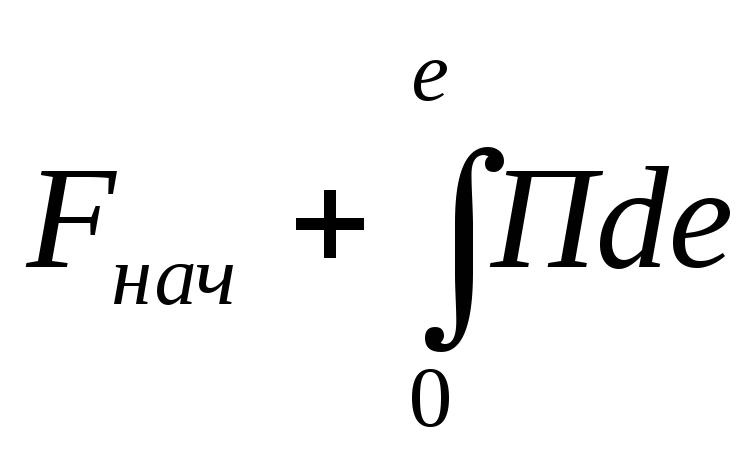 depending on the thickness of the burnt vault e there is an assumption about the uniformity of the fuel burning rate And=
de/
dt
throughout the entire charge volume. This means that charge combustion occurs in parallel (more precisely, equidistant) layers (Fig. 2.4).
depending on the thickness of the burnt vault e there is an assumption about the uniformity of the fuel burning rate And=
de/
dt
throughout the entire charge volume. This means that charge combustion occurs in parallel (more precisely, equidistant) layers (Fig. 2.4). /
/ (cf. paragraph 3.1.1), in this section the pressure is determined by the system of equations (0
  e
e  e 0):
e 0): ;
; .
. S
S
 ;
; ;
; ;
; .
. looks like
  , Where P,
I
, Where P,
I And
And  - initial thrust, specific impulse and mass of the stage, respectively.
 - relative deviations of the burning rate from its average (formular) value;
  -
relative pressure dispersion from the average value due to random deviations of charge and engine parameters (see subsection 3.4);
-
relative pressure dispersion from the average value due to random deviations of charge and engine parameters (see subsection 3.4);  T 3
-
random changes in charge temperature in a narrow range of temperature control modes.
T 3
-
random changes in charge temperature in a narrow range of temperature control modes.
 T 3 takes into account the entire temperature range under given application conditions
 .
. (e)
in the pressure drop section, it is necessary to take into account the inhomogeneities of the combustion rate throughout the entire volume of the charge and random deviations of its geometric characteristics. With a known dependence S
(e)
in the pressure drop section, it is necessary to take into account the inhomogeneities of the combustion rate throughout the entire volume of the charge and random deviations of its geometric characteristics. With a known dependence S  (e) pressure is calculated using the previous system of equations, adjusted to take into account changes in the amount of gas in the volume of the solid propellant rocket engine.
Solid propellant rocket engine (solid propellant rocket motor)


